Product image for Square D LC1D09T7 600 VAC 9 Amp 3-Pole 1NO 1NC Screw Terminal Full Voltage Non-Reversing IEC Contactor
Image thumbnail 0
Image thumbnail 2
Image thumbnail 3
Image thumbnail 4
Image thumbnail 5
Image thumbnail 6
Image thumbnail 7

Email

Square D LC1D09T7 600 VAC 9 Amp 3-Pole 1NO 1NC Screw Terminal Full Voltage Non-Reversing IEC Contactor

Manufacturer: Square-D / Schneider | Catalog # LC1D09T7 | Cooper Electric Part # 254903

$111.67/ea
ea
Log in or register to view your price, purchase history, and more!
Out of stock, please contact your sales representative for availability, pricing and lead times
TeSys D contactors have been designed for perfect integration into control systems. They can be used to create motor starters for almost any type of application. TeSys D contactors are available in 13 contactor ratings for inductive motor applications up to 150 full-load amps and resistive loads up to 200 amps. This 9A inductive 3 pole IEC contactor can be mounted on DIN rail or mounted directly to a panel. Contactors have both Horsepower and Kw motor rating for international acceptance. Contactor is rated for 20HP at 200-208VAC, 25HP at 240VAC, 60HP at 480VAC and 60HP at 600VAC three phase. Contactor is also rated for 7.5HP at 115VAC and 15HP at 240VAC single phase. When used with a 480VAC up to 35A circuit breaker, this contactor can have a SCCR up to 85kA. When used with up to a 600VAC 25A Class J or CC fuse, this contactor can have a SCCR up to 100kA. Contactor is supplied with a 80 VAC 50/60 Hz coil. Contactor has one normally open and one normally closed auxiliary contact built-in as standard. The NC contact is mirror certified. Screw clamp terminals are used for load and auxiliary connections. An extensive line of accessories makes it easy to meet the requirements of most applications. The contactor is 3.15 inches tall, 1.77 inches wide and 3.39 inches deep. It weighs 0.71 lbs. Contactor is certified to UL, CSA, IEC, CCC, EAC and Marine standards. Contactor also meets the requirements of RoHS/REACh making it a Green Premium product.

Technical Information

Applications
Resistive load;Motor control
Coil Voltage
480 V AC 50/60 HZ,POWER CIRCUIT <= 690 V AC 25...400 HZ-POWER CIRCUIT <= 300 V DC
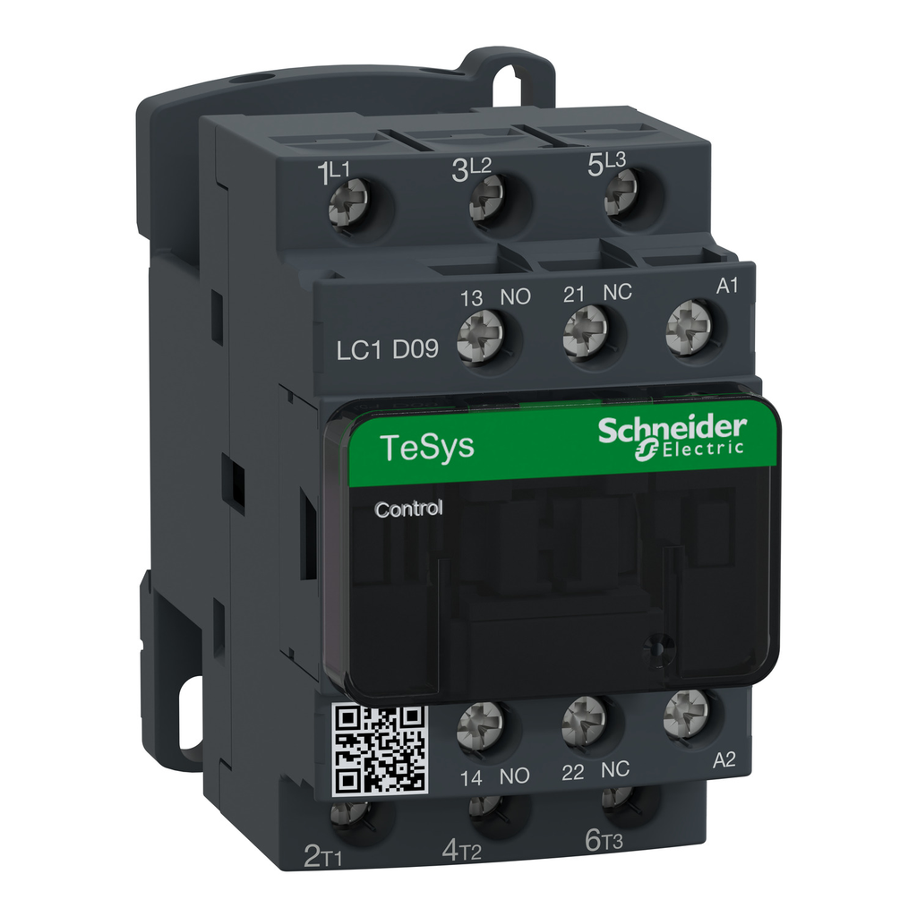
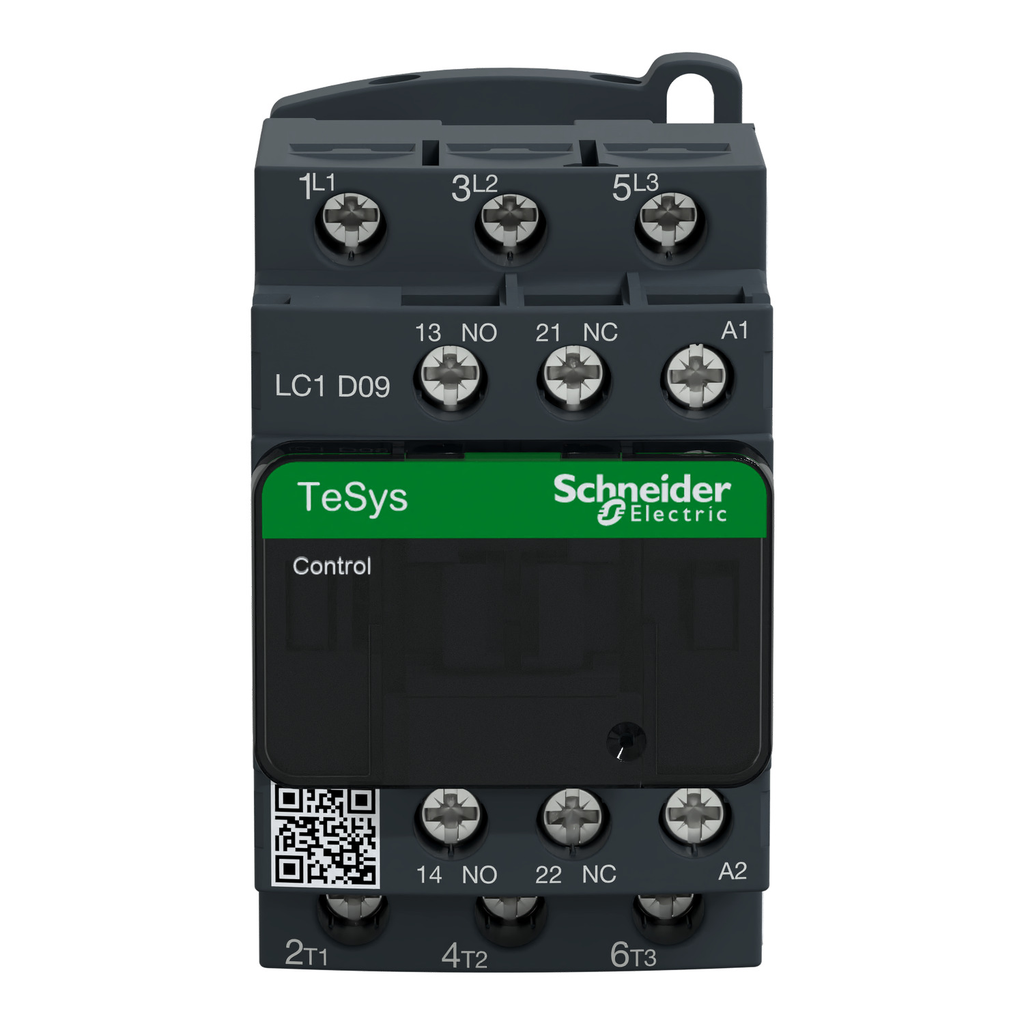
Contact Configuration
1 NO + 1 NC,3 NO
Contact Rating
25 A 60 AC POWER CIRCUIT-10 A 60 AC SIGNALLING CIRCUIT
Impedance
2.5 MOhm - Ith 25 A 50 Hz For Power Circuit
Net Weight
0.32 kg
Operating Cycles
3600 cyc/h 60 C
Operating Temperature
-40-70 Adegrees C AT UC,-5-60 Adegrees C
Range
TeSys
Size
45 MM,77 MM,86 MM
Standard
CSA C22.2 No 14,EN 60947-4-1,EN 60947-5-1,IEC 60335-1,IEC 60947-4-1,IEC 60947-5-1,UL 508
Storage Temperature
-60-80 degrees C
TC Connection
POWER CIRCUIT SCREW CLAMP TERMINALS 1 1-4 MMAFLEXIBLE WITHOUT CABLE END-CONTROL CIRCUIT SCREW CLAMP TERMINALS 2 1-2.5 MMAFLEXIBLE WITH CABLE END-CONTROL CIRCUIT SCREW CLAMP TERMINALS 1 1-4 MMASOLID WITHOUT CABLE END-CONTROL CIRCUIT SCREW CLAMP TERMINALS 2 1-4 MMASOLID WITHOUT CABLE END-POWER CIRCUIT SCREW CLAMP TERMINALS 2 1-4 MMAFLEXIBLE WITHOUT CABLE END-POWER CIRCUIT SCREW CLAMP TERMINALS 1 1-4 MMAFLEXIBLE WITH CABLE END-POWER CIRCUIT SCREW CLAMP TERMINALS 2 1-2.5 MMAFLEXIBLE WITH CABLE END-POWER CIRCUIT SCREW CLAMP TERMINALS 1 1-4 MMASOLID WITHOUT CABLE END-POWER CIRCUIT SCREW CLAMP TERMINALS 2 1-4 MMASOLID WITHOUT CABLE END-CONTROL CIRCUIT SCREW CLAMP TERMINALS 1 1-4 MMAFLEXIBLE WITHOUT CABLE END-CONTROL CIRCUIT SCREW CLAMP TERMINALS 2 1-4 MMAFLEXIBLE WITHOUT CABLE END-CONTROL CIRCUIT SCREW CLAMP TERMINALS 1 1-4 MMAFLEXIBLE WITH CABLE END
Type
Contactor
Voltage
300 Volt
Wattage
1.56 Watt AC-1 - 0.2 Watt AC-3

Manufacturer Information

Brand
Schneider Electric
Sub Brand
TeSys D;TeSys Deca

General Product Info

12-Digit UPC
338911034884
GTiN
03389110348811
Product UPC
78590120694
Weight
0.32 kg

Dimensions

Depth
3.39 in
Height
3.03 in
Warranty Length
18 mth
Width
1.77 in

Certifications and Compliance

CA Prop65 Warning
WARNING: This product can expose you to chemicals including: Antimony oxide & Antimony trioxide, which is known to the State of California to cause cancer. For more information go to www.P65Warnings.ca.gov
Certifications
BV,CB,CCC,CSA,DNV,GL,GOST,LROS (Lloyds Register Of Shipping),RINA,UKCA,UL
Country of Origin
Indonesia
Insulation Resistance
  • > 10 MOhm for signalling circuit
Heat Dissipation
  • 2-3 W at 50/60 Hz
Inrush Power In VA
  • 70-70 VA 60 Hz cos phi 0.75 (at 20 °C)
  • 70-70 VA 50 Hz cos phi 0.75 (at 20 °C)
  • 70-70 VA 50 Hz cos p
Connections Terminals
  • power circuit: screw clamp terminals 1 1-4 mm² - cable stiffness: flexible without cable end
  • power circuit: screw clamp terminals 1 1-4 mm² - cable stiffness: fl
IE Rated Operational Current
  • 9 A (at <60 °C) at <= 440 V AC AC-3 for power circuit
  • 9 A (at <60 °C) at <= 440 V AC AC-3 fo
ITH Conventional Free Air Thermal Current
  • 25 A (at 60 °C) for power circuit
  • 10 A (at 60 °C) for signalling circuit
CAD
  • https://download.schneider-electric.com/files?p_Doc_Ref=LC1D09_12_18_0_OD
  • https://download.schneider-electric.com/files?p_Doc_Ref=LC1D09T7_CAD
  • https://download.schneider-electric.com/files?p_Doc_Ref=MCADPP0003369_3D-CAD&p_File_name=MCADPP0003369_3D-simpl
IP Degree Of Protection
  • IP20 front face IEC 60529
Climatic Withstand
  • IACS E10 exposure to damp heat
  • IEC 60947-1 Annex Q category D exposure to damp heat
Power Dissipation Per Pole
  • 1.56 W AC-1
  • 0.2 W AC-3
  • 0.2 W AC-3e
Maximum Operating Rate
  • 3600 cyc/h at 60 °C
Prop 65
  • WARNING: This product can expose you to chemicals including: Antimony oxide & Antimony trioxide, which is known to the State of California to cause cancer. For more information go to www.P65Warnings.ca.gov
Carbon Footprint Of The Installation Phase A5
  • 0 kg CO2 eq.
  • 0.023894932466090976
Non Overlap Time
  • 1.5 ms on de-energisation between NC and NO contact
  • 1.5 ms on energisation between NC and NO contact
Carbon Footprint Of The End Of Life Phase C1 To C4
  • 0.7750113583608836
  • 0.8 kg CO2 eq.
Standards
  • CSA C22.2 No 14
  • EN 60947-4-1
  • EN 60947-5-1
  • IEC 60947-4-1
  • IEC 60947-5-1
  • UL 60947-4-1
  • IEC 60335-1:Clause 30.2
  • IEC 60335-2-40:Annex JJ
  • UL 60335-2-40:Annex JJ
  • CSA C22.2 No 60947-4-1
Operating Time
  • 12...22 ms closing
  • 4...19 ms opening
Control Circuit Type
  • AC 50/60 Hz
Minimum Switching Voltage
  • 17 V for signalling circuit
UC Control Circuit Voltage
  • 480 V AC 50/60 Hz
ICW Rated Short Time Withstand Current
  • 105 A 40 °C - 10 s for power circuit
  • 210 A 40 °C - 1 s for power circuit
  • 210 A 40 °C - 1 s for power circui
Related Products
  • with
  • LADN22
  • LADN11
  • LADN20
  • LAD8N11
  • LADT2
  • LADN40
  • LAD6K10M
Carbon Footprint Of The Manufacturing Phase A1 To A3
  • 2 kg CO2 eq.
  • 1.9114422288716764
Protective Treatment
  • THIEC 60068-2-30
UI Rated Insulation Voltage
  • power circuit 690 V IEC 60947-4-1
  • power circuit 600 V CSA
  • power circuit 600 V UL
  • signalling
Average Impedance
  • 2.5 mOhm - Ith 25 A 50 Hz for power circuit
Accessories
  • LAD9V2
  • LAD9R1V
  • LAD9R1
Electrical Durability
  • 0.6 Mcycles 25 A AC-1 <= 440 V
  • 2 Mcycles 9 A AC-3 <= 440 V
  • 2 Mcycles 9 A AC-3
Maximum Horse Power Rating
  • 1 hp at 230/240 V AC 50/60 Hz for 1 phase motors
  • 2 hp at 2
Market Segmentation
  • Commercial
  • Industrial
Persona Type Names
  • End User
  • Contractor
  • Original Equipment Manufacturer
  • OEM - Control Panelbuilder
  • Panel Builder
  • System Integrator
Fire Resistance
  • 850 °C IEC 60695-2-1
Contactor Application
  • resistive load
  • motor control
Motor Power KW
  • 2.2 kW at 220...230 V AC 50/60 Hz (AC-3)
  • 4 kW at 380...400 V AC 50/60 Hz (AC-3)
  • 4 kW at 38
Flame Retardance
  • V1 conforming to UL 94
Carbon Footprint Of The Use Phase B2 B3 B4 B6
  • 16 kg CO2 eq.
  • 15.510153788942613
Accessory Products
  • LAD9V2
  • LAD9R1V
  • LAD9R1
Persona Type Ids
  • EU
  • LC
  • OM
  • OM8
  • PB
  • SI
Auxiliaries
  • LADN22
  • LADN11
  • LADN20
  • LAD8N11
  • LADT2
  • LADN40
  • LAD6K10M
Safety Reliability Level
  • B10d = 1369863 cycles contactor with nominal load EN/ISO 13849-1
  • B10d = 1369863 cycles contactor with nominal load EN/ISO 13
Carbon Footprint Of The Distribution Phase A4
  • 0.14851165558038001
  • 0.1 kg CO2 eq.
Tightening Torque
  • power circuit 1.7 N.m screw clamp terminals flat Ø 6 mm
  • power circuit 1.7 N.m screw cl
Mechanical Robustness
  • vibrations contactor open 2 Gn, 5...300 Hz)
  • vibrations contactor closed 4 Gn, 5...300 Hz)
  • vibrations contactor closed 4
Minimum Switching Current
  • 5 mA for signalling circuit
Control Circuit Voltage Limits
  • 0.3...0.6 Uc (-40-70 °C):drop-out AC 50/60 Hz
  • 0.8...1.1 Uc (-40-60 °C)
Market Segmentation Id
  • COMMERCIAL
  • INDUSTRIAL
IRMS Rated Making Capacity
  • 250 A at 440 V for power circuit conforming to IEC 60947
  • 140 A AC for signalling ci
Associated Fuse Rating
  • 10 A gG for signalling circuit conforming to IEC 60947-5-1
  • 25 A gG at <= 690
Hold In Power Consumption In VA
  • 7.5-7.5 VA 60 Hz cos phi 0.3 (at 20 °C)
  • 7-7 VA 50 Hz cos phi 0.3 (at 20 °C)
  • 7-7 VA 50 Hz cos phi 0
UE Rated Operational Voltage
  • power circuit <= 690 V AC 25...400 Hz
  • power circuit <= 300 V DC
Permissible Ambient Air Temperature Around The Device
  • -40-60 °C
  • 60-70 °C with derating
Rated Breaking Capacity
  • 250 A at 440 V for power circuit conforming to IEC 60947
UIMP Rated Impulse Withstand Voltage
  • 6 kV IEC 60947


Compare