Image thumbnail 1
Image thumbnail 2
Image thumbnail 3
Image thumbnail 4
Image thumbnail 5
Image thumbnail 6

Email

SQUARED LC1D128FD IEC contactor, Te

Manufacturer: Square-D / Schneider | Catalog # LC1D128FD | Cooper Electric Part # 1044230

$170.28/ea
ea
Log in or register to view your price, purchase history, and more!
Out of stock, please contact your sales representative for availability, pricing and lead times
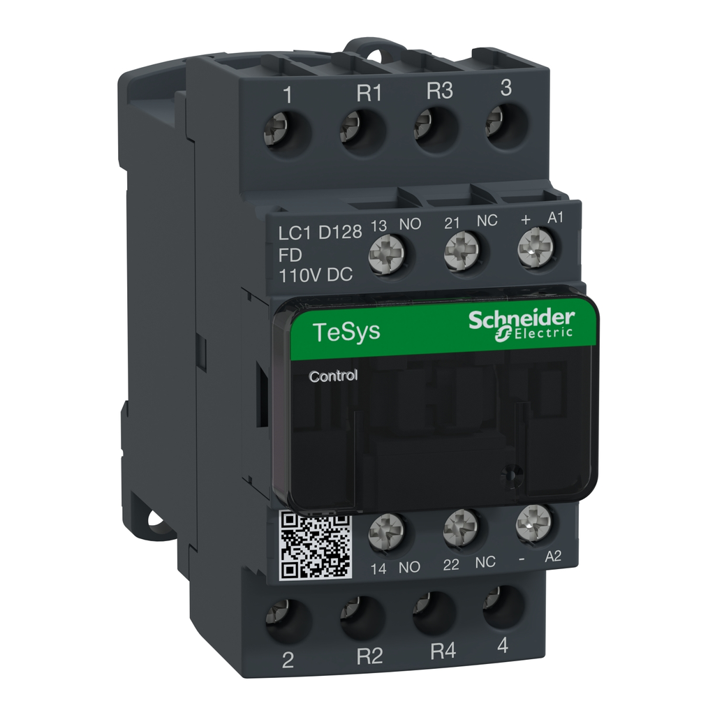
TeSys Deca contactor, 4 poles (2NO+2NC), for non-inductive load applications up to 25A/690V AC-1. They can be used to create motor starters for almost any type of application. It provides a 110V DC coil with transient suppressor module, 1NO+1NC built-in auxiliary contacts (NC mirror certified), connection by screw clamp terminals. For operating rates until 3600 cycles/hour and environments until 60.C, it procures high reliability and durability. Compact (45mm width), DIN-rail mounting or screw fixing. Power contacts have a 25A resistive load rating. Multi standards certified (IEC, UL, CSA, CCC, EAC, Marine). Contactor has one normally open and one normally closed auxiliary contact built-in as standard. The NC contact is mirror certified. Screw clamp terminals are used for load and auxiliary connections. An extensive line of accessories makes it easy to meet the requirements of most applications. The contactor is 3.35 inches tall, 1.77 inches wide and 3.90 inches deep. It weighs 1.16 lbs. Contactor is certified to UL, CSA, IEC, CCC, EAC and Marine standards.

Technical Information

Applications
RESISTIVE LOAD
Coil Voltage
110 V DC,POWER CIRCUIT <= 690 V AC 25...400 HZ-POWER CIRCUIT <= 300 V DC
Contact Configuration
1 NO + 1 NC,2 NO + 2 NC
Contact Rating
25 A 60 AC POWER CIRCUIT-10 A 60 AC SIGNALLING CIRCUIT
Impedance
2.5 MOhm - Ith 25 A 50 Hz For Power Circuit
Net Weight
0.525 kg
Operating Cycles
3600 cyc/h 140 F (60 C)
Operating Temperature
-40-70 Adegrees C AT UC,-5-60 Adegrees C
Range
TeSys
Size
45 MM,85 MM,99 MM
Standard
CSA C22.2 No 14,EN 60947-4-1,EN 60947-5-1,IEC 60335-1,IEC 60947-4-1,IEC 60947-5-1,UL 508
Storage Temperature
-60-80 degrees C
TC Connection
POWER CIRCUIT SCREW CLAMP TERMINALS 1 1-4 MMAFLEXIBLE WITHOUT CABLE END-CONTROL CIRCUIT SCREW CLAMP TERMINALS 2 1-2.5 MMAFLEXIBLE WITH CABLE END-CONTROL CIRCUIT SCREW CLAMP TERMINALS 1 1-4 MMASOLID WITHOUT CABLE END-CONTROL CIRCUIT SCREW CLAMP TERMINALS 2 1-4 MMASOLID WITHOUT CABLE END-POWER CIRCUIT SCREW CLAMP TERMINALS 2 1-4 MMAFLEXIBLE WITHOUT CABLE END-POWER CIRCUIT SCREW CLAMP TERMINALS 1 1-4 MMAFLEXIBLE WITH CABLE END-POWER CIRCUIT SCREW CLAMP TERMINALS 2 1-2.5 MMAFLEXIBLE WITH CABLE END-POWER CIRCUIT SCREW CLAMP TERMINALS 1 1-4 MMASOLID WITHOUT CABLE END-POWER CIRCUIT SCREW CLAMP TERMINALS 2 1-4 MMASOLID WITHOUT CABLE END-CONTROL CIRCUIT SCREW CLAMP TERMINALS 1 1-4 MMAFLEXIBLE WITHOUT CABLE END-CONTROL CIRCUIT SCREW CLAMP TERMINALS 2 1-4 MMAFLEXIBLE WITHOUT CABLE END-CONTROL CIRCUIT SCREW CLAMP TERMINALS 1 1-4 MMAFLEXIBLE WITH CABLE END
Type
CONTACTOR
Voltage
300 Volt
Wattage
1.56 Watt AC-1

Manufacturer Information

Brand
Schneider Electric
Sub Brand
TESYS D

General Product Info

12-Digit UPC
389110404411
GTiN
03389110404418
Product UPC
78590143411
Weight
0.525 kg

Dimensions

Depth
3.9 in
Height
3.35 in
Warranty Length
18 mth
Width
1.77 in

Certifications and Compliance

CA Prop65 Warning
WARNING: This product can expose you to chemicals including: Antimony oxide & Antimony trioxide, which is known to the State of California to cause cancer. For more information go to www.P65Warnings.ca.gov
Certifications
BV,CB,CCC,CSA,DNV,GL,GOST,LROS (Lloyds Register Of Shipping),RINA,UKCA,UL
Country of Origin
Indonesia
Insulation Resistance
  • > 10 MOhm for signalling circuit
Connections Terminals
  • power circuit: screw clamp terminals 1 1-4 mm² - cable stiffness: flexible without cable end
  • power circuit: screw clamp terminals 2 1-4 mm² - cable stiffness: flexible without cable end
  • power circuit: screw clamp terminals 1 1-4 mm² - cable stiffness: flexible with cable end
  • power circuit: screw clamp terminals 2 1-2.5 mm² - cable stiffness: flexible with cable end
  • power circuit: screw clamp terminals 1 1-4 mm² - cable stiffness: solid without cable end
  • power circuit: screw clamp terminals 2 1-4 mm² - cable stiffness: solid without cable end
  • control circuit: screw clamp terminals 1 1-4 mm² - cable stiffness: flexible without cable end
  • control circuit: screw clamp terminals 2 1-4 mm² - cable stiffness: flexible without cable end
  • control circuit: screw clamp terminals 1 1-4 mm² - cable stiffness: flexible with cable end
  • control circuit: screw clamp terminals 2 1-2.5 mm² - cable stiffness: flexible with cable end
  • control circuit: screw clamp terminals 1 1-4 mm² - cable stiffness: solid without cable end
  • control circuit: screw clamp terminals 2 1-4 mm² - cable stiffness: solid without cable end
IE Rated Operational Current
  • 25 A (at <60 °C) at <= 440 V AC AC-1 for power circuit
ITH Conventional Free Air Thermal Current
  • 25 A (at 60 °C) for power circuit
  • 10 A (at 60 °C) for signalling circuit
CAD
  • https://download.schneider-electric.com/files?p_Doc_Ref=LC1D098BD_3D-simplified
  • https://download.schneider-electric.com/files?p_Doc_Ref=MCADPP0003710_3D-CAD&p_File_name=MCADPP0003710_3D-simplified.stp
  • https://download.schneider-electric.com/files?p_Doc_Ref=MCADPP0003710_3D-CAD&p_File_name=MCADPP0003710_2D-back.dwg
  • https://download.schneider-electric.com/files?p_Doc_Ref=MCADPP0003710_3D-CAD&p_File_name=MCADPP0003710_2D-back.dxf
  • https://download.schneider-electric.com/files?p_Doc_Ref=MCADPP0003710_3D-CAD&p_File_name=MCADPP0003710_2D-bottom.dwg
  • https://download.schneider-electric.com/files?p_Doc_Ref=MCADPP0003710_3D-CAD&p_File_name=MCADPP0003710_2D-bottom.dxf
  • https://download.schneider-electric.com/files?p_Doc_Ref=MCADPP0003710_3D-CAD&p_File_name=MCADPP0003710_2D-front.dwg
  • https://download.schneider-electric.com/files?p_Doc_Ref=MCADPP0003710_3D-CAD&p_File_name=MCADPP0003710_2D-front.dxf
  • https://download.schneider-electric.com/files?p_Doc_Ref=MCADPP0003710_3D-CAD&p_File_name=MCADPP0003710_2D-isometric.dwg
  • https://download.schneider-electric.com/files?p_Doc_Ref=MCADPP0003710_3D-CAD&p_File_name=MCADPP0003710_2D-isometric.dxf
  • https://download.schneider-electric.com/files?p_Doc_Ref=MCADPP0003710_3D-CAD&p_File_name=MCADPP0003710_2D-left.dwg
  • https://download.schneider-electric.com/files?p_Doc_Ref=MCADPP0003710_3D-CAD&p_File_name=MCADPP0003710_2D-left.dxf
  • https://download.schneider-electric.com/files?p_Doc_Ref=MCADPP0003710_3D-CAD&p_File_name=MCADPP0003710_2D-right.dwg
  • https://download.schneider-electric.com/files?p_Doc_Ref=MCADPP0003710_3D-CAD&p_File_name=MCADPP0003710_2D-right.dxf
  • https://download.schneider-electric.com/files?p_Doc_Ref=MCADPP0003710_3D-CAD&p_File_name=MCADPP0003710_2D-top.dwg
  • https://download.schneider-electric.com/files?p_Doc_Ref=MCADPP0003710_3D-CAD&p_File_name=MCADPP0003710_2D-top.dxf
IP Degree Of Protection
  • IP20 front face IEC 60529
Climatic Withstand
  • IACS E10 exposure to damp heat
  • IEC 60947-1 Annex Q category D exposure to damp heat
Power Dissipation Per Pole
  • 1.56 W AC-1
Maximum Operating Rate
  • 3600 cyc/h at 60 °C
Prop 65
  • WARNING: This product can expose you to chemicals including: Antimony oxide & Antimony trioxide, which is known to the State of California to cause cancer. For more information go to www.P65Warnings.ca.gov
Carbon Footprint Of The Installation Phase A5
  • 0 kg CO2 eq.
  • 0.04109287085369836
Non Overlap Time
  • 1.5 ms on de-energisation between NC and NO contact
  • 1.5 ms on energisation between NC and NO contact
Carbon Footprint Of The End Of Life Phase C1 To C4
  • 1.3003129381185559
  • 1 kg CO2 eq.
Standards
  • CSA C22.2 No 14
  • EN 60947-4-1
  • EN 60947-5-1
  • IEC 60947-4-1
  • IEC 60947-5-1
  • UL 60947-4-1
  • IEC 60335-1:Clause 30.2
  • IEC 60335-2-40:Annex JJ
  • UL 60335-2-40:Annex JJ
  • CSA C22.2 No 60947-4-1
Operating Time
  • 63 15 % ms closing
  • 20 20 % ms opening
Control Circuit Type
  • DC standard
Minimum Switching Voltage
  • 17 V for signalling circuit
UC Control Circuit Voltage
  • 110 V DC
ICW Rated Short Time Withstand Current
  • 105 A 40 °C - 10 s for power circuit
  • 210 A 40 °C - 1 s for power circuit
  • 30 A 40 °C - 10 min for power circuit
  • 61 A 40 °C - 1 min for power circuit
  • 100 A - 1 s for signalling circuit
  • 120 A - 500 ms for signalling circuit
  • 140 A - 100 ms for signalling circuit
Related Products
  • with
  • LADN22
  • LADN11
  • LADN20
  • LADT2
  • LADN40
  • LADN31
  • LADN02
  • LADT0
  • LADS2
  • LADR2
Carbon Footprint Of The Manufacturing Phase A1 To A3
  • 3 kg CO2 eq.
  • 2.6849853456684607
Protective Treatment
  • THIEC 60068-2-30
UI Rated Insulation Voltage
  • power circuit 690 V IEC 60947-4-1
  • power circuit 600 V CSA
  • power circuit 600 V UL
  • signalling circuit 690 V IEC 60947-1
  • signalling circuit 600 V CSA
  • signalling circuit 600 V UL
Average Impedance
  • 2.5 mOhm - Ith 25 A 50 Hz for power circuit
Electrical Durability
  • 0.8 Mcycles 25 A AC-1 <= 440 V
Market Segmentation
  • Commercial
  • Industrial
Persona Type Names
  • End User
  • Contractor
  • Original Equipment Manufacturer
  • OEM - Control Panelbuilder
  • Panel Builder
  • System Integrator
Inrush Power In W
  • 5.4-5.4 W 20 °C)
Fire Resistance
  • 850 °C IEC 60695-2-1
Flame Retardance
  • V1 conforming to UL 94
Carbon Footprint Of The Use Phase B2 B3 B4 B6
  • 41 kg CO2 eq.
  • 40.7366918918919
Persona Type Ids
  • EU
  • LC
  • OM
  • OM8
  • PB
  • SI
Auxiliaries
  • LADN22
  • LADN11
  • LADN20
  • LADT2
  • LADN40
  • LADN31
  • LADN02
  • LADT0
  • LADS2
  • LADR2
Safety Reliability Level
  • B10d = 1369863 cycles contactor with nominal load EN/ISO 13849-1
  • B10d = 20000000 cycles contactor with mechanical load EN/ISO 13849-1
Carbon Footprint Of The Distribution Phase A4
  • 0.14839419227412126
  • 0.1 kg CO2 eq.
Tightening Torque
  • power circuit 1.7 N.m screw clamp terminals flat Ø 6 mm
  • power circuit 1.7 N.m screw clamp terminals Philips No 2
  • control circuit 1.7 N.m screw clamp terminals flat Ø 6 mm
  • control circuit 1.7 N.m screw clamp terminals Philips No 2
  • control circuit 1.7 N.m screw clamp terminals pozidriv No 2
  • power circuit 1.7 N.m screw clamp terminals pozidriv No 2
Mechanical Robustness
  • vibrations contactor open 2 Gn, 5...300 Hz)
  • vibrations contactor closed 4 Gn, 5...300 Hz)
  • shocks contactor open 10 Gn for 11 ms)
  • shocks contactor closed 15 Gn for 11 ms)
Minimum Switching Current
  • 5 mA for signalling circuit
Control Circuit Voltage Limits
  • 0.1...0.25 Uc (-40-70 °C):drop-out DC
  • 0.7...1.25 Uc (-40-60 °C):operational DC
  • 1...1.25 Uc (60-70 °C):operational DC
Hold In Power Consumption In W
  • 5.4-5.4 W 20 °C
Market Segmentation Id
  • COMMERCIAL
  • INDUSTRIAL
IRMS Rated Making Capacity
  • 250 A at 440 V for power circuit conforming to IEC 60947
  • 140 A AC for signalling circuit conforming to IEC 60947-5-1
  • 250 A DC for signalling circuit conforming to IEC 60947-5-1
Associated Fuse Rating
  • 10 A gG for signalling circuit conforming to IEC 60947-5-1
  • 40 A gG at <= 690 V coordination type 1 for power circuit
  • 25 A gG at <= 690 V coordination type 2 for power circuit
UE Rated Operational Voltage
  • power circuit <= 690 V AC 25...400 Hz
  • power circuit <= 300 V DC
Permissible Ambient Air Temperature Around The Device
  • -40-60 °C
  • 60-70 °C with derating
Rated Breaking Capacity
  • 250 A at 440 V for power circuit conforming to IEC 60947
UIMP Rated Impulse Withstand Voltage
  • 6 kV IEC 60947


Compare